Procedure for performing a planned turn – head up orientation
The procedure for performing a planned turn with a radar in the Head Up orientation involves three steps:- planning the turn from a chart, setting up the radar and executing the turn.
Planning from the chart
The desired turn centre is identified, either by bisecting the initial track and next track and selecting an appropriate radius or drawing lines parallel to the initial and next track at a distance of a desired radius. (see figure 2a) The turn radius is noted. (see figure 2b).
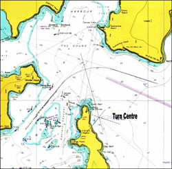 | 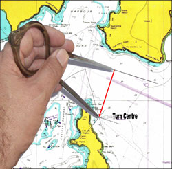 |
| figure 2a - establishing the turn centre | figure 2b - noting turn radius |
A conspicuous radar target is selected as the reference point (ideally the reference point will be abeam when the vessel completes the turn and steadies on the next track).
The distance of the reference point from the turn centre is measured. (see figure 3).
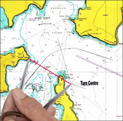
figure 3 – measuring the reference point distance from the turn centre
Setting up the radar
The head up orientation is selected with a range scale suitable for monitoring the turn. (Target wakes/trails feature is selected if available)
The VRM centre is offset abeam of the bow at the turn radius distance.
The VRM is set at the reference point distance from the turn centre.
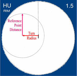
figure 4 – setting up the radar
Executing and monitoring the turn
When the selected reference point is about a ship’s length or less from touching the VRM, the turn is started. In a manner similar to parallel indexing to follow a straight track, the apparent path of the reference point can be kept on the circular path of the offset range ring by adjusting the vessel’s rate of turn.
figure 5 – circular path of reference point
Required rate of turn adjustments are immediately apparent by any divergence of the reference point’s track from the predicted relative track.
If the rate of turn is too low, the reference point will move below the VRM (figure 6a). In such a case the rate of turn must be increased to bring the reference point “back on track” (figure 6b).
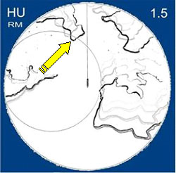 |  |
| figure 6a - initial turn rate too low | figure 6b - turn rate increased |
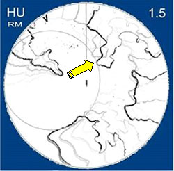
If the rate of turn is too high, the reference point will move above the VRM (figure 7a). In such a case the rate of turn must be decreased to bring the reference point “back on track” (figure 7b)
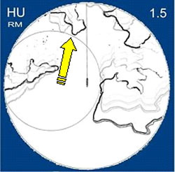 | 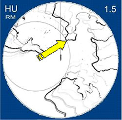 |
| figure 7a - initial turn rate too high | figure 7b - turn rate decreased |

It can be seen that if the turn is started too early or too late, the rate of turn can be adjusted to bring the reference point onto the VRM ring and thus bring the vessel back to the intended turn track.