Planning considerations – reference point selection
Sensitivity
It can be seen in the preceding animations that:
- Reference points directly above or below the VRM centre are the most sensitive to turn radius changes.
Reference points directly above and below the turn centre have a horizontal path.
Reference points on the beam are not sensitive to turn radius changes as their track is parallel to the vessel.
These factors are important in selecting the optimum target to monitor the turn or conversely, form part of the positioning criteria for navigaton markers.
The reference point used should:
- be visible on a range scale suitable to the manoeuvre
- be sensitive to turn radius changes to ensure completing the turn on the next track
- ideally have a distance from the turn centre greater than the turn radius
- not be lost to radar shadow sectors or sea clutter.
This discussion assumes the vessel closely follows the initial planned track, which is usually the case when navigating in confined waters. Subject to the reference point used, there may be considerable tolerance for cross track error on the initial track. Should that not be the case, a composite method can be employed. With a “wheel over” line (parallel to the next track) and the desired radius to come round to the next track, the VRM centre is offset at the desired radius, when the wheel over line is reached, the VRM is adjusted out to the reference point. The turn is then executed as discussed.
Refining reference point and radius selection
The effect of cross track error on the initial track is to displace the actual turn centre along an arc at the reference point distance around the reference point. (see figure 1)
If at the start of the next track this arc is nearly parallel to the next track, there will be considerable tolerance to cross track error on the initial track. This is shown in figure 1 with the result of cross track error being shown in green for right of track and red for left of track.
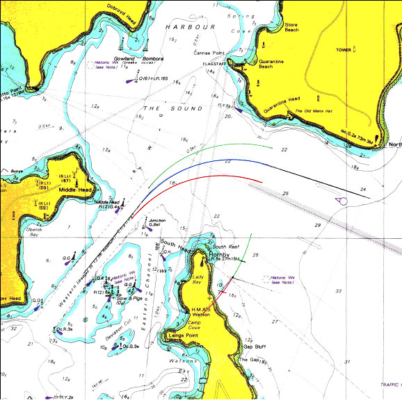
Figure 1 – Middle Head being used as the reference point
This demonstrates the benefit of selecting a reference point that will be abeam at the start of the next track. Similar tolerance to cross track error could be achieved by selecting a smaller radius and the more distant headland. (see figure 2)

Figure 2 – Grotto Point being used as the reference point with a smaller turn radius
In the example used in this paper, the radius and reference point distance were selected as they provide another reference point equidistant from the turn centre, (Quarantine Head). (see figure 3) This provides for detection of any departure from the planned turn with the additional benefit of one reference point increasing in sensitivity whilst the sensitivity of the other decreases.
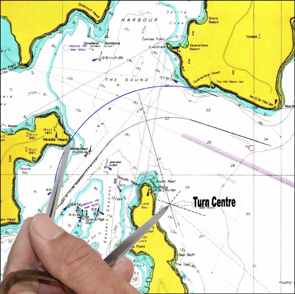
Figure 3. Middle Head and Quarantine Head equidistant from turn centre.